PARSP_274_01
TP SENSOR:
Absolute Throttle Position Sensor
(V) (%)
Unit Conversion Type: ANGLE
This sensor indicates the absolute throttle opening value as calculated from voltage input form TP sensor.
OPERATING RANGE (IDLE)
(Fully closed)
4% - 14%
-0.2V - 0.7V
(DBW)
4% - 20%
0.2V - 1.0V
PARSP_06_01
BARO SENSOR:
Barometric Pressure Sensor
(V)(kPa)(MPa)(kgf/cm2)(mmHg)(inHg)(psi)
(N/A : Not equipped)
Unit Conversion Type: PRESSURE
The barometric pressure sensor is located inside the PCM. The sensor detects barometric pressure and converts it into voltage. The signal is used to correct injection time for changing altitude and atmospheric conditions. The voltage becomes lower as atmospheric pressure decreases, and the voltage becomes higher as atmospheric pressure increases.
There are two different sensors used, each having different voltage characteristics. The most widely used is shown as Type A in the graph below. It will typically read near 2.88 V at sea level. Type B was introduced on some models in 2008. It will typically read near 4.08 V at sea level.
i: Type B
ii: Type A
iii: Pressure at Sea Level
X: Barometric Pressure
Y: Sensor Input
NOTE: At times you may be requested to compare the MAP and BARO sensors to each other with the Key On Engine Off (KOEO). The voltage and pressure values on a Type A BARO and a MAP sensor should read near each other. The voltage value of a Type B BARO sensor will not read the same as the MAP sensor. If you change the unit conversion from voltage to pressure, the values should then be close to the same.
PARSP_82_01
CLV:
Calculated Load Value
(%)
Calculated load value refers to the current air flow divided by peak air flow.
It indicates the percentage of engine capacity being used.
OPERATING RANGE (IDLE)
20% - 43%
PARSP_273_01
MAF SENSOR:
Mass Air Flow Sensor
(V) (g/s)
Unit Conversion Type: AIR FLOW
A sensor indicates the amount of air flowing into the engine.
PARSP_05_01
MAP SENSOR:
Manifold Absolute Pressure Sensor
(V)(kPa)(MPa)(kgf/cm2)(mmHg)(inHg)(psi)
Unit Conversion Type: PRESSURE
- The sensor detects the intake manifold pressure, converts it into the voltage by the semiconductor, and sends it to the control unit. The signal is used for determination of the basic injection time together with the engine speed signal output from the crankshaft angle sensor.
- The manifold absolute pressure sensor is installed between the throttle valve of the throttle body and the intake manifold, and it detects the intake manifold vacuum to calculate intake air amount.
- The vacuum generated in the intake manifold is applied to the silicon diaphragm (sensor element). The silicon diaphragm is an element that changes the electric resistance value by the applied pressure. A voltage is pre-applied to the electrode provided in the diaphragm, and current value changes according to pressure change. This current change is converted into voltage change by the amplifier, and the sensor signal is output.
- The sensor signal operates the amplifier by the reference voltage (5V) supplied from the VCC. The amplifier generates a signal based on this voltage, and outputs it to the ECU.
- The voltage becomes lower with larger intake manifold vacuum, and the voltage becomes higher with smaller intake manifold vacuum. This change is in proportion to the vacuum generated in the intake manifold.
- With this vacuum signal, the computer calculates the amount of intake air based on the engine speed and throttle position.
- The manifold absolute pressure sensor detects the intake air density from the throttle valve position and engine load status change (high/low) from the intake air vacuum of the intake manifold.
- The manifold absolute pressure sensor has the unit structure with an amplifier, which is the amplifier circuit supplied the reference voltage from the ECU. The sensor detects intake air vacuum by the pressure sensor, amplifies it by the amplifier, and converts it into the signal voltage. The signal voltage is low at vacuum side, and high at atmosphere pressure side.
- Reference operating range (idle) 28kPa - 41kPa, 0.55V - 1.8V

i: Amplifier
ii: Sensor element
iii: VCC
iv: SG
v: PB
vi: ECU
vii: Reference voltage circuit
viii: Computer

Fig: Vacuum voltage characteristics
Y: V
X: mmhg
i: Atmosphere
NOTE: At times you may be requested to compare the MAP and BARO sensors to
each other with the Key On Engine Off (KOEO).
Use parameter specification kPa for BARO SENSOR.
PARSP_04_01
IAT SENSOR / IAT SENSOR 1:
Intake Air Temperature Sensor / Intake Air Temperature Sensor(1)
(°C) (°F) (V)
Unit Conversion Type: TEMPERATURE
- The intake air temperature sensor is installed on the intake manifold. The sensor detects the intake air temperature change using the thermistor that changes its resistance value according to the temperature, and converts it into the signal voltage.
- The structure and property of the resistance value are the same as those of the engine coolant temperature sensor, however, the thermistor wall is thinner and made of resin for better response.
- Reference operating range (idle) 25°C - 90°C, 2.8V - 1.7V

Fig: Temp. voltage characteristics
Y: V
X: °C
4R_FI_TW2_ECT2A
ECT SENSOR 2 :
Engine Coolant Temperature Sensor 2
(°C) (°F) (V)
Unit Conversion Type: TEMPERATURE
This indicates the engine coolant temperature on the radiator side.
This ECT sensor is mounted to the radiator side for determining a stuck-closed
thermostat.
PARSP_03_01
ECT SENSOR / ECT SENSOR 1 :
Engine Coolant Temperature Sensor / Engine Coolant Temperature Sensor 1
(°C) (°F) (V)
Unit Conversion Type: TEMPERATURE
- The sensor detects the coolant temperature change via resistance value change of the thermistor, converts it into voltage, and sends it to the control unit. With this signal (voltage), the basic injection time is corrected according to the coolant temperature. The resistance value of the thermistor becomes higher with lower coolant temperature, and the value becomes lower with higher temperature.
- The engine coolant temperature sensor is a thermistor sensor installed to the block, and it detects engine coolant temperature.
- The thermistor changes its resistance value according to the temperature, and the resistance value change is in proportion to the temperature. Therefore, the thermistor is placed into the coolant, and the sensor detects the resistance value change and converts it to coolant temperature change.
- The resistance value change for the temperature (temperature resistance characteristics) is as shown in the figure. When the thermistor detects lower temperature, the resistance value becomes higher, and it detects higher temperature, the value becomes lower.
- The thermistor detects the resistance value as temperature, and the computer cannot detect the resistance value. Therefore, the value needs to be converted into the voltage value which can be detected by the computer.
- To convert into the voltage value, the voltage of 5V is output by the reference voltage circuit in the ECU, and applied it to the thermostat. The thermostat has a circuit that consumes a certain voltage out of the 5V depending on the resistance value, and current values in the circuit change resulting in voltage change.
- The voltage becomes higher (5V), as the temperature becomes lower, and it becomes lower, as the temperature becomes higher. Because this voltage change is in proportion to the resistance change, the temperature can be detected by the computer.
- The engine coolant temperature sensor is installed on the cylinder block, and it detects engine coolant temperature change. The engine coolant temperature sensor uses the thermostat that changes its resistance value according to the temperature. The resistance value becomes higher with lower coolant temperature, and it becomes lower with higher temperature. The signal voltage is output based on the resistance value change of the thermostat.
- Reference operating range (idle) 70°C- 100°C, 1.0V - 0.4V

Fig: Temp. resistance characteristics
Y: kΩ
X: °C

i: Sensor
ii: TW
iii: SG
iv: ECU
v: Reference voltage circuit
vi: Computer
PARSP_02_01
VEHICLE SPEED:
Vehicle Speed
(km/h) (MPH)
Unit Conversion Type: VEHICLE SPEED
The vehicle speed (km/h) is converted by ECU from the pulse signal sent from
the vehicle speed sensor for display. When the drive wheel speed is 2km/h or
higher, the ECU controls various functions using the wheel speed information.
Examples)
ON/OFF control of V TEC system Fuel-cut control at high speed driving Control of
air fuel ratio correction during driving.
- The vehicle speed sensor is also used for the speedometer. The pulse signal is output from the sensor based on the vehicle speed, and the vehicle speed (km/h) is calculated from the number of pulses within the specified time.
- The vehicle speed sensor system detects the differential gear rotation by the magnet integrated in the rotor and Hall element installed outside of the magnet. When voltage is applied to the Hall element and magnetic flux is changed, Hall voltage is output based on the magnetic flux change. Because the Hall voltage changes in four cycles during one rotor rotation, the waveform creation circuit outputs four-pulse signal.
- When the vehicle speed becomes higher, number of the vehicle speed signal pulse within the specified time increases, and voltage is output with approximately 7pulses/s at 10km/h, and 707pulses /s at 100km/h.
- The signal voltage output from the vehicle speed sensor is a pulse signal, and voltage of 0V and 5V is output alternately. When the vehicle speed sensor signal is OF, the voltage (5V) output from reference circuit of the computer in the ECU flows to the vehicle speed sensor and becomes 0V, and when the vehicle speed sensor signal is ON, the reference voltage becomes 5V at the same potential.
- The computer detects the vehicle speed signal based on ON/OFF switching of the reference voltage which is made by ON/OFF switching of the vehicle speed sensor. - The vehicle sensor detects the vehicle speed change based on final gear rotation speed on the transmission.
- The vehicle speed sensor has a magnetic sensing element and detects magnetic flux change. This change is amplified and converted into Hi and Lo voltage signals. The magnetic flux changes depending on the rotation speed of the magnetic rotor installed on rotation area of the final gear.

i: Magnet
ii: Hall element
iii: Waveform creation circuit
iv: Vehicle speed signal output

Fig: Output waveform of vehicle speed signal
Y: V
X: Time

Fig: Vehicle speed sensor (Training text III)
i: IG
ii: Vehicle speed sensor
iii: VSP
iv: ECU
v: Reference voltage circuit
vi: Computer
vii: SG
PARSP_01_01
ENGINE SPEED:
Engine Speed
(RPM)
Engine speed is converted from CKP sensor.
PARSP_295_01
AF SENSOR:
A/F Sensor
(mA)
A sensor that detects the amount of oxygen content in the exhaust gases.
4R_FI_RDBWRLY
THROTTLE ACTUATOR SUPPLY VOLTAGE :
Throttle Actuator Supply Voltage
(OFF/ON)
This indicates ON when TACM(Throttle Actuator Control Module) relay applied.
PARSP_286_01
TACM RELAY:
Throttle Actuator Control Module Relay
(ON/OFF)
This relay is controlled by the ECM and supplies power to the TAC module.
It indicates ON when the ECM turns ON.
PARSP_283_01
CRUS REQ TH:
Requested Throttle valve Position by Cruise Control Module
(°)
This indicates the throttle position requested by the cruise control.
PARSP_284_01
MOTOR DUTY:
Motor Output Duty
(%)
Output duty of motor controlled by TACM(Throttle Actuator Control Module).
PARSP_279_01
TP SENSOR-B:
Throttle Position Sensor B
(V)
This sensor is a supplemental sensor.
The ECM/PCM compares the voltage from throttle position sensor A and throttle
position sensor B to detect failures.
PARSP_278_01
TP SENSOR-A:
Throttle Position Sensor A
(V)
A potentiometer connected to the throttle valve shaft.
It indicates the actual voltage on the TP sensor A.
PARSP_280_01
IDLE TARGET TH:
Target Throttle Valve Position at Idle
(°)
This indicates the target angle based on engine rotation and the amount of air flow.
PARSP_277_01
TARGET TH VLV:
Target Throttle Valve Position (ETCS)
(°)
The ECM calculates the target angle from the accelerator position sensor input and the driving conditions.
PARSP_276_01_OBS
THROTTLE VLV :
Throttle Valve
(deg)
Valid data range & sampling interval
This On Board Snapshot parameter is available only following range and sampling interval.
-10 to 0 (sec): 0.1 sec sampling
Regards to On-Board Snapshot after 12MY, both the value outside of the recording length and the value between recording points shall be shown as "***".
PARSP_289_01
APP SENSOR-B:
Acceleration Pedal Position Sensor B
(V)
A potentiometer connected to the accelerator pedal cable.
This indicates half the voltage value of APP sensor A.

A: APP SENSOR A
B: APP SENSOR B
i : The depressed amount of the accelerator pedal
PARSP_288_01
APP SENSOR-A:
Acceleration Pedal Position Sensor A
(V)
A potentiometer connected to the accelerator pedal cable.

A: APP SENSOR A
B: APP SENSOR B
i : The depressed amount of the accelerator pedal
PARSP_290_01
APP SENSOR:
Acceleration Pedal Position Sensor
(%)
It indicates the depressed amount of the accelerator pedal.
PARSP_367_01
REL TP SENSOR:
Relative Throttle Position Sensor
(%) (°)
Unit Conversion Type: ANGLE
This signal displays the throttle opening, relative to the fully closed position, where "0" is the fully closed position.
It is different from TP SENSOR, which displays the absolute throttle position, where "0" is perpendicular to the throttle bore.
OPERATING RANGE (IDLE)
(DBW idle)
0 - 5 [%]
0 - 4 [°]

A : Default position (When IG SW is on)
B : Fully closed position (0°)
4R_FI_ISO2HT
HO2S S2 HEATER CURRENT:
HO2S S2 Heater Current
(A)
It indicates the drive current of O2 sensor heater.
4R_FI_CAN_DSO2HT
HO2S HEATER DUTY:
(%)
This parameter displays the heater ON duty for Heated Oxygen Sensor (HO2S).
To stabilize its output, HO2S has an internal heater.
Duty control can realize high accurate heater control rather than ON/OFF control.

A: SHO2S
B: SG
C: SO2SHTC
D: ECM/PCM
E: SECONDARY HO2S (SENSOR 2)
F: IG1
G: IGNITION SWITCH
PARSP_112_01
HO2S S2 HEATER:
Oxygen Sensor Sensor 2 Heater
(ON/OFF)
A heater that stabilizes oxygen sensor performance and gets it working
sooner.
It turns off if the battery voltage is above 16 volts.
OPERATING RANGE (IDLE)
(ON)
PARSP_89_01
HO2S S2:
Heated Oxygen Sensor Sensor 2
(V)
A heated oxygen sensor installed after catalyst to represent double oxygen sensor feedback and to examine primary oxygen sensor performance.
OPERATING RANGE (IDLE)
0.00V - 1.40V
PARSP_17_01
Oxygen Sensor Heater:
HO2S (AF) S1 HEATER
(ON/OFF)
- The data is indicated with ON/OFF.
- ON/OFF of the oxygen sensor heater is controlled by the ECU, and it is normally ON. It turns OFF if the coolant temperature is 0°C or lower, the battery voltage is above 16V, or when the engine is stopped.
Reference operating range (Idle)
(ON)
PARSP_87_01
FSS:
Fuel System Status
OL COND : Open loop due to conditions
CLOSED : Closed loop
OL DRV : Open loop due to driving
OL DTC : Open loop due to DTC
CL O2SX : Closed loop but faulty O2S
This indicates the feedback condition and the reason why the fuel system is in a given operating mode.
PARSP_86_01
LT FUEL TRIM:
Long Term Fuel Trim
(Counts)
Air fuel feedback average (AF FB AVE) is used by the PCM to detect long term failures in the air fuel control system. The fuel system is too rich when AF FB AVE drops below the lower limit threshold while the purge control solenoid is turned off. The fuel system is too lean when AF FB AVE rises above the upper limit threshold.
AF FB AVE generally chases AF FB, updating about once a minute. However AF FB AVE may remain much lower than AF FB depending on the amount of fuel vapors stored in the EVAP canister. An AF FB AVE value near the lower limit threshold may be normal depending on the value of AF FB.
NORMAL OPERATION - LOW CANISTER FUEL VAPOR SATURATION

A : AF FB (ST FUEL TRIM)
B : AF FB AVE (LT FUEL TRIM)
C : Threshold line
The graph above shows the AF FB value operating near the ideal value of 1.00. AF FB AVE is slowly chasing AF FB and is also staying near 1.00.
NORMAL OPERATION - HIGH CANISTER FUEL VAPOR SATURATION

A : AF FB (ST FUEL TRIM)
B : AF FB AVE (LT FUEL TRIM)
C : Threshold line
In the case of a saturated EVAP canister, AF FB may be reading normally but AF FB AVE will drop near or below the lower limit threshold. The PCM has logic to prevent a DTC from setting during this condition. The graph above shows the AF FB value reading normally and the AF FB AVE at the lower limit threshold. When this occurs, the PCM cuts purge operation and sees if AF FB AVE begins to return toward 1.00. If AF FB AVE increases above a certain threshold, the monitor is paused for a set time and purge is turned back on to remove excess purge vapor from the canister. The monitor is resumed after the set time expires.
TOO LEAN

A : AF FB (ST FUEL TRIM)
B : AF FB AVE (LT FUEL TRIM)
C : Threshold line
The graph above shows the AF FB value operating above the upper limit threshold. AF FB AVE slowly chased AF FB above the threshold causing a DTC to set.
TOO RICH

A : AF FB (ST FUEL TRIM)
B : AF FB AVE (LT FUEL TRIM)
C : Threshold line
The graph above shows the AF FB value operating below the lower limit threshold. AF FB AVE slowly chased AF FB below the threshold causing a DTC to set.
4R_FI_CAN_DAFHT
AF HEATER:
(%)
This parameter displays LAF sensor heater ON duty.
0% means Heater OFF.

A: AFS+
B: AFS-
C: AFSHTC
D: SUBRLY
E: MRLY
F: ECM/PCM
G: A/F SENSOR (SENSOR 1)
H: PGM-FI SUBRELAY
I: PGM-FI MAIN RELAY 1
J: BATTERY
PARSP_85_01
AF FB (ST FUEL TRIM):
Short Term Fuel Trim
(Counts)
Air fuel feedback is a short term correction to fuel delivery. The base value is 1.00. A value greater than 1.00 indicates injector duration is being increased and a value less than 1.00 indicates injector duration is being decreased.
Air Fuel Ratio Leaner Than Command

The graph above shows the PCM using AF FB (ST FUEL TRIM) to correct an air fuel ratio that became too lean. The actual air fuel ratio shown in green reached about 16.8, much leaner than the command air fuel ratio of 14.79 shown in blue. In response the PCM increased injector duration by increasing the air fuel feedback value shown in red from 1.03 to 1.06. The additional amount of fuel caused the air fuel ratio to drop back down toward the commanded air fuel ratio of 14.79.
Air Fuel Ratio Richer Than Command

The graph above shows the PCM using AF FB (ST FUEL TRIM) to correct an air fuel ratio that became too rich. The actual air fuel ratio shown in green reached about 13.8, much richer than the command air fuel ratio of 14.79 shown in blue. In response the PCM decreased injector duration by decreasing the air fuel feedback value shown in red from 1.06 to 1.03. The lower amount of fuel caused the air fuel ratio to rise back toward the commanded air fuel ratio of 14.79.
4R_FI_CAN_AFRAC
AF SENSOR IMPEDANCE:
(Ohm)
LAF sensor (DENSO) impedance.
When LAF sensor is driven, the valid data is replied.
A: AFS+
B: AFS-
C: AFSHTC
D: SUBRLY
E: MRLY
F: ECM/PCM
G: A/F SENSOR (SENSOR 1)
H: PGM-FI SUBRELAY
I: PGM-FI MAIN RELAY 1
J: BATTERY
4R_FI_CAN_AFCAD
AF SENSOR SIGNAL PLUS:
(V)
This parameter displays the AFS+ line voltage for LAF sensor.
A: AFS+
B: AFS-
C: AFSHTC
D: SUBRLY
E: MRLY
F: ECM/PCM
G: A/F SENSOR (SENSOR 1)
H: PGM-FI SUBRELAY
I: PGM-FI MAIN RELAY 1
J: BATTERY
4R_FI_CAN_AFVAD
AF SENSOR SIGNAL MINUS:
(V)
This parameter displays the AFS- line voltage for LAF sensor.
A: AFS+
B: AFS-
C: AFSHTC
D: SUBRLY
E: MRLY
F: ECM/PCM
G: A/F SENSOR (SENSOR 1)
H: PGM-FI SUBRELAY
I: PGM-FI MAIN RELAY 1
J: BATTERY
4R_FI_CAN_CMDEQRAT_KCMD
AF FB CMD:
Air Fuel Ratio Feedback Command
The target air/fuel ratio that the ECM controls from the oxygen sensor data.
The reciprocal of AF FB CMD is A/F LAMBDA CMD.
4R_FI_CAN_CMDEQRAT
A/F LAMBDA CMD
Air Fuel Lambda Command
This is equivalent to Commanded Equivalence Ratio.
NOTE: Commanded Equivalence Ratio is defined in Service$01 PID $44 specified in SAE J1979/ISO 15031-5.
The reciprocal of A/F LAMBDA CMD is AF FB CMD.
A/F Command
<primary O2 sensor>
Fuel system that utilise conventional oxygen sensor shall display the commanded
open loop equivalence ratio while the fuel control system is in open loop. A/F
shall indicate about 1.0 while in closed loop fuel.
<primary LAF sensor>
Fuel system that utilise wide-range/linear oxygen sensors shall display the
command equivalence ratio in both open loop and closed loop operation.
·open loop···A/F sensor F/B
·close loop···A/F sensor NO F/B

For example,for gasoline,stoichiometric is 14.64:1 ratio.
If the fuel control system was commanding an 0.95 A/F the commanded A/F ratio to
the engine would be 14.64*0.95=13.9A/F.
4R_FI_LAMBDA_AFR
AIR FUEL RATIO:
Air Fuel Ratio
This indicates the Air Fuel Ratio calculated from A/F LAMBDA.
NOTE: Air Fuel Ratio = 14.7*A/F LAMBDA
PARSP_298_01
AF LAMBDA:
A/F Sensor Equivalence Ratio
This indicates the equivalence ratio which is the current measured air/fuel ratio divided by the stoichiometric A/F ratio.
LAMBDA > 1 Lean
LAMBDA < 1 Rich
4R_FI_CAN_TAC_ACET
A/C TEMPERATURE SENSOR:
Air Conditioning Temperature Sensor
(°C) (°F) (V)
Unit Conversion Type: TEMPERATURE
It indicates the air conditioner evaporator temperature sensor output which input to FI ECU. It is A/C air conditioner evaporator temperature.
If there is no input from the sensor to FI ECU, this parameter will display the value when open circuit(i.e. -40degC) is happened.
FI ECU uses this information when to operate A/C clutch.
If this sensor has failure or line open/short between sensor and FI ECU, A/C clutch will not be ON.
NOTE:This parameter may display the value when open circuit(i.e. -40degC) when A/C clutch operation is no problem.
Then, please check ECM/PCM input terminal for this sensor.
You can find out the terminal is not connected to the sensor.
In this case, FI ECU received the sensor output from air conditioner control unit thru CAN newtwork, and it is used for A/C clutch operation.
4R_FI_ACRPS_ACRP
A/C PRESSURE SENSOR :
A/C Pressure Sensor
(V) (kPa) (MPa) (kgf/cm2) (psi)
The A/C pressure sensor measures the pressure in the high side of the A/C system.
4R_FI_CAN_ACS
A/C SWITCH:
A/C Switch
(ON/OFF)
A/C switch data list goes to ON when the following conditions are met:
- Thermal protector is in the closed position.
- A/C pressure switch is closed (above 28 psi and below 455 psi).
- A/C switch is in the ON position.
- Heater fan switch is in position 1,2,3, or 4.
A 5V reference is sent from the PCM through all the closed switches through the heater fan switch (only in positions 1,2,3 or 4) to body ground (5V reference needs to see a path to ground).
A/C switch data list goes to OFF when the following conditions are met:
- Anyone of the switches is in the open position.
- Heater fan speed is in the OFF position.
- The 5V reference has no path to ground.
NOTE: This parameter may be displayed even if the vehicle does not equip the A/C system.
In this case, the value will be OFF. This is not problem.
PARSP_36_01
BRAKE SWITCH:
Brake Switch
(ON/OFF)
- This sensor detects the operation status of the brake pedal. The brake lamp switch voltage is used for signal. When the brake pedal is not operated, the BKSW terminal does not output the voltage. When the brake pedal is depressed, the switch turns ON, and the brake lamp illuminates. As a result, the battery voltage is applied to the BKSW terminal, and BKSW terminal outputs the voltage. When the voltage from this terminal is ON, the computer detects the brake pedal operation.

i: IG
ii: Brake switch
iii: Brake light
iv: Oil pressure switch
v: PSW
vi: BKSW
vii: ECU
viii: Reference voltage circuit
ix: Computer
4R_FI_CAN_CRTMSW
CLUTCH PEDAL POSITION SWITCH B:
Clutch Pedal Position Switch B
(OPEN/CLOSE)
AT control unit send the open signal to PGM-FI unit when the clutch pedal is depressed
and PGM-FI unit will cancel the auto cruse.
Cruise control system cancellation request input from AT shift selector switches or MT gear lever.
If you step on clutch pedal lightly,cruise control will be cancelled in few seconds.
AT control unit will send this signal when the clutch pedal is depressed five seconds or more.
This signal has five seconds delay to avoid the frequent cancel for auto cruse.
Note:Cruise control Not support vehicle value of the unit is "CLOSE".
PARSP_219_01
A/T R SWITCH:
A/T R Position Switch
(ON/OFF)
When the A/T shift lever is shifted to the R position, the A/T R switch
indicates ON to the ECM (electrically closed).
PARSP_31_01
PNP SWITCH:
A/T Park/Neutral Position Switch
(P-N/GEAR)
When the A/T shift lever is shifted to "P" or "N" position, the PNP switch
indicates P-N to the ECM (electrically closed).
If it is in gear, the PNP switch indicates GEAR.
PARSP_270_01
GEAR POSITION:
Gear Position
This shows the estimated gear position is calculated from both of the Main shaft speed sensor and the Countershaft speed sensor.
After IG ON, this parameter shows "Neutral or unknown".
After engine is started, ECU estimated gear position as like below figure image.
Example) This parameter shows "1" at A. When the vehicle condition is changed from A to B, this parameter shows "2". In the same way, this parameter value will be from "2" to "1" when the vehicle status is changed from B to A.

Fig: Image of the routine to estimate gear position (6th gear position)
X: Engine speed (Main shaft speed)
Y: Vehicle speed (Countershaft speed)
NOTE:
PARSP_27_01
ELD:
ELD
- The ELD unit detects the magnetic flux generated in the main wire harness of the vehicle, by the pickup for the magnetic flux detection. This magnetic flux is in proportion to the current amount of the harness, therefore, increase/decrease of electric power consumption can be detected by monitoring the magnetic flux.
- Increase/decrease amount of the electric power consumption is output to the PGM-FI ECU via the signal output circuit.
- The output signal of the electric power consumption has characteristics in which consumption increases, as the signal voltage decreases.
- The ELD sensor is installed on the main fuse box. It detects the electric load amount used via the vehicle from the current flow of the main power harness.
- The ELD sensor has the unit structure with an amplifier. It detects the load current change of the vehicle by the current sensor, amplifies it by the amplifier, and converts it into the signal voltage.

Fig: ELD unit
i : Pick-up
ii : IG1
iii : ELD unit
iv : Detection circuit
v : Signal output circuit
vi : ACG
vii : EL
viii: ACGC
ix :ACGF
x : ECU
xi : Detection circuit
xii: Control signal
xiii: Detection circuit
xiv: Computer

Fig: Signal output characteristics
Y : V
X : Electric power consumption
PARSP_317_01
IG1 LEVEL:
IG1 Voltage Level
(HIGH/LOW)
It indicates the IG1 voltage level.
PARSP_26_01
BATTERY:
Battery Voltage (V)
Standard condition:12V
The battery is charged from the generator at about 12V to 15V while the engine
is running.
BATTERY indicates the battery voltage whenever ignition switch is on.
4R_FI_FCDEC
FUEL CUT DECEL :
Fuel Cut Decel
(ON/OFF)
This parameter displays the status of the operation mode of the control module used to turn off the fuel injectors during certain deceleration conditions.
4R_FI_FC
FUEL CUT :
Fuel Cut
(ON/OFF)
This parameter displays the status of the operation mode of the control module used to turn off the fuel injectors.
4R_FI_IDLING
IDLING :
Idling
(ON/OFF)
With the ignition switch ON, the engine running at idle, this will be ON. Depressing the accelerator pedal while idling will turn it OFF.
PARSP_321_01
KNOCK CTRL :
Knock Control
It indicates the IG timing correction when the control module is adjusting the IG timing to alleviate excessive engine knock.
4R_FI_CAN_MBKSAD
KNOCK SENSOR(Circuit Diag):
(V)
NOTE: To judge occurrence of knocking and/or knock system performance, please use the parameters "KNOCK RETARD" and "KNOCK CTRL".
PARSP_53_01
KNOCK RETARD:
Knock Retard
This status indicates that the ECU retards the specified degree of the ignition timing from the basic ignition timing to prevent knocking based on the signal from the knock sensor.
When the knock signal indicating abnormal combustion of the engine is sent from the knock sensor to the ECU, the ECU retards the specified degree of the ignition timing from the basic ignition timing to prevent knocking.
Knock control
Knocking is closely related to the ignition timing. When the ignition timing is advanced, the maximum combustion pressure increases, thus the knocking tendency also increases.
OPERATING RANGE (IDLE) 0°
PARSP_52_01
SPARK ADVANCE:
Spark Advance Angle Degrees
(°)
Various sensors input to the ECM so that ignition timing can be optimized for
different driving conditions.
It is the advance angle of number 1 cylinder.
OPERATING RANGE (IDLE)
13° - 18°
PARSP_51_01
INJECTOR:
Injector
- This status indicates that the ECU transmits the determined injection amount to the injector.
- The ECU determines the optimum injection amount depending on the engine operating conditions using the signals from all the sensors, actuators, relays, and valves.
- The injector is a solenoid valve which supplies the optimum amount of fuel depending on the engine operating conditions. The pressure-adjusted fuel is supplied to the injector where it is measured and injected into the intake manifold with the minimum valve opening time. This enables the optimum fuel supply. In addition, as the engine operation range changes from idling to medium speed, and finally to the top speed, it requires the instantaneous measurement and injection depending on the situation. For this reason, the injector is a resistor-integrated type with improved response.
(1) Injector activation
- When the solenoid coil is energized, the magnetic flux generated on the coil energizes the core. Then the core is pulled and moves into the solenoid coil by overcoming the solenoid spring force. At this time, the needle valve also moves together with the core. This makes the needle valve and valve seat of the valve body separated and the fuel is injected. The measurement amount is calculated using the coil energization time and the pre-applied fuel pressure.
(2) Resistor operation
- The resistor improves the injector response. As the engine speed increases, the time-based energization count (ON/OFF) of the coil also increases. The increased alternative resistance prevents the current flowing smoothly. At this time, the injector functions to improve the response of the solenoid coil.
(3) Injector operation
- After the computer determines the operation time (injection time), the voltage signal transmitted from the main relay via the resistor injector to the drive circuit turns ON the drive circuit. The drive current flows to the solenoid coil of the injector to generate the operation waveform which controls the coil.
- The injector starts operation gradually when receiving the operation ON signal by the operation waveform generated on the coil. The operation time until the injector is completely operated (the valid operation time) is considered as the invalid operation time. The total operation time includes this invalid time.
- When the operation signal is turned OFF, the counter electromotive voltage rises rapidly on the coil. This risen voltage ensures that the injection properly completes.
- The injector is a solenoid valve which is required high opening/closing precision, response, endurance. It consists of plunger, needle valve, core, solenoid coil, filter, and valve.
- The fuel supplied via the inside of the injector is injected through the needle valve. The fuel lubricates and cools the injector to stabilize the temperature of the needle valve. The injection amount is adjusted by changing ON time of ON/OFF output signals synchronized with the engine speed signal.
<Current flow>
- The injector power is supplied from the battery via the main relay when the ignition is turned ON. The ground is made in the ECU to activate the injector.
<Operation>
1. After the ECU determines the injection time, the fuel injector is energized.
2. This energizes the solenoid coil to pull the core.
3. Because the needle valve and plunger are integrated with the core, the needle valve lifts.
4. The inside of the injector is filled with the pressurized fuel. When the needle valve lifts, the fuel is injected through the tip of the injector.
5. The lift amount of the injector needle valve is set to the specified amount, and the fuel pressure is maintained at the specific value by the pressure regulator. Therefore, the injection amount is determined by the valve opening time (energization time of the solenoid valve).
- Reference operating range (idle) 1.5ms - 3.5ms

Fig: Injector drive signal, waveform characteristics
Y: V
X: Time
i : Drive waveform
ii: Inefficient drive time
iii: Efficient drive time
iv: Drive signal
v : ON
vi: OFF
4R_FI_CNDOLVL
ENGINE OIL LEVEL MONITOR CONDITION:
Engine Oil Monitor Condition
(ACTIVE) (INACTIVE)
4R_FI_LOIL
ENGINE OIL LEVEL:
Engine Oil Level
(mm)
4R_FI_CAN_RVTS
SOLENOID RETURN SIGNAL:
Solenoid Return Signal
(ON/OFF)
It indicates ON when the VTS circuit is normal and VTS is ON.
When the circuit has a problem, it stays ON or OFF.
PARSP_50_01
VTEC SOL:
VTEC Solenoid Valve (Spool Valve)
(ON/OFF)
The ECM opens the solenoid valve to change the actuation of engine valve timing
and lift to improve performance.
The change point depends on the engine load conditions.
4R_FI_CAN_EGRST
EGR FLOW OPEN RATIO:
(%)
This is diagnostic result information about Exhaust Gas Recirculation (EGR) Insufficient Flow (P0401).
This is the ratio of current EGR flow to pre-determined normal EGR flow.
(EGR FLOW OPEN RATIO) = (Current EGR Flow) / (Pre-determined Normal EGR Flow)
When this parameter shows 100%, it means this system is normal and there is no EGR passage clogged. If this parameter is malfunction threshold or less, system will be malfunction and EGR passage is clogged.
Then P0401shall be occurred. The malfunction threshold is different by each model. Refer to "Advanced Diagnostic" information for each model.
For Example: Regards to 12MY FIT AT, the threshold is 20%.
NOTE: If the monitor of P0401 is not executed in this drive cycle, this parameter will show "0%".
Moreover, Enable condition of P0401 is different between each model. Refer to "Advanced Diagnostics" for each model.
General Description: The EGR valve is closed during deceleration with the throttle valve fully closed. Then the ECM/PCM fully opens the EGR valve. After a set time, the ECM/PCM computes the ratio of the present EGR flow to the normal EGR flow by monitoring the fluctuation of the intake manifold pressure between when the EGR valve is fully opened and when it is fully closed. Then, ECM/PCM diagnoses P0401.
Throttle Valve

EGR Valve

MAP Sensor

Engine Speed

A: Open
B: Close
C: High
D: Low
E: Actual
F: Command
G: Threshold for P0401
H: When EGR flow rate is 100%
Fig: P0401 General description
PARSP_56_01
EGR valve position sensor (EGR VLS):
EGR Lift Sensor
(V)
- The EGR control reduces NOX in the exhaust gas. It recirculates the exhaust gas into the intake manifold, and mix it into intake mixture to reduce the combustion temperature.
(1) Activation
- When the computer determines the recirculation amount of EGR, the EGR control SOL V is activated, and the intake manifold vacuum is applied to the diaphragm of the EGR valve, then, the valve connected to the diaphragm opens. As a result, the exhaust gas from the exhaust manifold flows into the intake manifold.
- The EGR valve has the valve position sensor, and the computer detects the lift amount of the valve. Therefore, it controls the drive signal (ES) sent to the EGR control SOL V via the valve position sensor signal (EGRL) to obtain the required recirculation amount.
(2) Control signal
- The voltage of the EGR valve position sensor signal becomes higher according to the valve position. The voltage changes in proportion to the valve position. Therefore, when the valve position calculated by the computer is not obtained, the EGR control SOL V is activated to obtain it.
- The drive signal (ES) of the EGR control SOL V is the duty signal. When the ON time is long, the vacuum inflow amount applied to the diaphragm of the EGR valve increases, and the lift amount of the EGR valve also increases.
- The exhaust gas recirculation unit has the EGR valve with the valve position sensor. It feedbacks the actual lift amount to the ECU to compare it with the target lift amount in order to improve fuel economy and engine performance, and to reduce NOX level.
The EGR valve is operated by the mixture vacuum, which consists of the vacuum that is controlled to the fixed value by the vacuum control valve, and the secondary air that is taken through the EGR control solenoid valve. In each operation range when the engine is cold, at idling, high speed, high load, and deceleration, the EGR operation is cancelled to secure the engine performance.
<Operation> In the EGR operation range, when the ECU receives the signals from the sensors, it opens/closes the EGR control solenoid valve to obtain the memorized target lift amount, and controls the CLOSE time (duty time). When the EGR valve opens (lifts), the valve position sensor detects the opening amount (lift amount), and it is sent to the ECU. Based on this signal, the ECU controls the EGR valve to obtain the target lift amount.
- Reference operating range (no lift) 0.95V - 1.50V

Fig: Lift sensor signal
Y: V

Fig: EGR control sol. valve drive signal
Y: V
X: Time
i: OFF
ii: ON
PARSP_136_01
EGR LIFT:
EGR Valve Lift
EGR LIFT:(actual) The EGR control reduces NOX in the exhaust gas. It recirculates the exhaust gas into the intake manifold, and mix it into intake mixture to reduce the combustion temperature. The maximum lift quantity: 5 mm.
PARSP_137_01
EGR L COMMAND:
EGR Valve Lift Command
EGR L COMMAND:(command) The EGR control reduces NOX in the exhaust gas. It recirculates the exhaust gas into the intake manifold, and mix it into intake mixture to reduce the combustion temperature. The maximum lift quantity: 5 mm.
4R_FI_CAN_OPSWR
OIL PRESSURE SWITCH :
Engine Oil Pressure Switch : Engine oil lamp light up when Engine pressure abnormal
(ON/OFF)
Status of OPSW (Engine Oil Pressure Switch) signal input.
PARSP_46_01
SCS:
Service Check Signal
(OPEN/SHORT)
When the SCS line is grounded, the Service Check Signal indicates SHORT.
After turning on the ignition switch, the indicator light blinks the DTCs.
4R_FI_CAN_ACC
A/C CLUTCH:
Air Conditioning Clutch
(ON/OFF)
The magnetic clutch is engaged when A/C switch is turned ON and the compressor
pressure switch and thermostat change to ON.
NOTE: This parameter may be displayed even if the vehicle does not equip the A/C system.
In this case, the value will be OFF. This is not problem.
4R_FI_CAN_DOCAT
CATA MONITOR CONDITION:
Catalytic System Monitoring Efficiency Condition
(OK/NG)
This indicates the efficiency condition to detect catalytic system deterioration.
PARSP_315_01
START IAT:
Intake Air Temperature at Start Up
(°C) (°F)
Unit Conversion Type: TEMPERATURE
This indicates the intake air temperature when the ignition switch is turned ON.
PARSP_316_01
START ECT:
Water Temperature at Start Up
(°C) (°F)
Unit Conversion Type: TEMPERATURE
This indicates the engine coolant Temperature when the ignition switch is turned (ON)
PARSP_268_01
MAX ENG SPD:
Maximum Engine Speed
(RPM)
This parameter displays the engine speed when an Engine Over-Speed Condition is detected. If an Engine Over-Speed Condition has not been detected, 0 is display.
PARSP_243_01
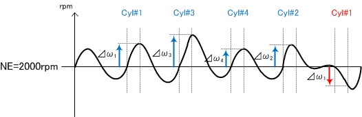
CKP
PULSER F/B LEARN:
CKP Pulser Feed Back Learn Condition
(Completed/Not Completed)
This shows whether the vehicle has learned misfire detection and enhancement of accuracy.It indicates 'Completed' if this learning has been completed.
<Enable Criteria>
ECT at 176°F(80°C) or higher.
<Procedure>
Test-drive the vehicle on a level road. Decelerate (with the throttle fully
closed) from an engine speed of 2,500 rpm to 1,000 rpm with the A/T in 2
position or M/T in 1st gear.
PARSP_151_01
IDLE TARGET:
Target idle speed
(RPM)
Calculated target idle RPM in ECM.
The target idle speed varies with the engine coolant water temperature or the engine load, etc.

i:Idle speed
ii:Engine coolant water temperature
ii-i:Low
ii-ii:High
iii:MT,AT/CVT(Neutral)
iv:AT/CVT(In gear)

i:Idle speed
ii:Engine load
ii-i:Low
ii-ii:High
iii:No load - Low load
iv:Medium load(Such as Small Light)
v:High load(Such as Head Light + Air/Con)
The PCM controls the idle speed so that the target idle speed set in advance meets the actual idle speed by comparing both values.
When the actual idle speed is lower than the target idle speed and the state that the difference is more than
a specified value continues for more than a specified time, it is determined as the failure of the idle speed control system. (Too Low = P0506)
Contrarily, when the idle speed is higher than the target idle speed and the state that the difference is more than
a specified value continues for more than a specified time, it is also determined as the failure of the idle speed control system. (Too High = P0507)
PARSP_145_01
IMMOBILIZER:
Immobilizer
(BAN/RUN)
BAN : Immobilizer module prevents ECM from starting the engine.
RUN : Immobilizer module allows ECM to start the engine.
PARSP_176_01
FAN HIGH CTRL:
Fan High Control
(ON/OFF)
When 2-stage radiator fan is controlled to high mode by ECM, the fan high control indicates ON.
PARSP_177_01
FAN LOW CTRL:
Fan Low Control
(ON/OFF)
When 2-stage radiator fan is controlled to low mode by ECM, the fan low control indicates ON.
PARSP_70_01
MAIN RELAY(FP):
Main Relay for Fuel Pump
(ON/OFF)
The main relay contains two individual relays.
This is the 2nd relay, which supplies power to the fuel pump.
PARSP_325_01
IMT(IMRC) VALVE CMD:
Intake Manifold Tuning (Intake Manifold Runner Control) Valve Command
(OPEN/CLOSE)
Two air intake paths are provided in the intake manifold.
The valve is closed at low engine speed.
PARSP_349_01
MIL DIST :
Distance since MIL on
(km) (mile)
Unit Conversion Type: DISTANCE
This indicates the distance that has elapsed since the ECM last commanded the MIL on.
PARSP_142_01
MIL STATUS:
MIL Status
(ON/OFF)
ON : The MIL is turned on and ECM stores MIL indicated DTCs.
OFF : The MIL is not turned on.
PARSP_66_01
MIL:
Malfunction Indicator Lamp
(ON/OFF)
- The malfunction indicator lamp is an actuator which indicates the operating status and the system status of the computer in the ECU. The operating condition and the system status are indicated by ON/OFF of the MIL.
- When the ignition switch is turned ON, the main power of the ECU (IGP) is supplied, with which the computer is also activated. If there is no failure in the system, the OFF signal is output to the drive circuit of the MIL. The drive circuit is turned OFF by the OFF signal, which causes the MIL to be OFF.
- If the computer detects the system failure during driving, it performs the fail-safe control, and outputs the ON signal to the drive circuit. The drive circuit is turned ON by the signal, which causes the MIL to be ON.
- With the MIL is remained ON, if the ignition switch is turned OFF once, the fail-safe control is reset and the MIL goes OFF. Then the normal control is restored, and the MIL is remained OFF until the failure is detected again.
- If the engine will not start and the MIL remains ON, it indicates the computer is not operating.
- The drive signal from the computer is used to switch ON (illuminating) and OFF(not illuminating) the voltage applied from IGN to the drive circuit in the ECU via the MIL. If the drive signal is not output by the computer, the drive circuit itself is turned ON to illuminate the MIL.

Fig: Malfunction indicator lamp
i : IG
ii: Malfunction indicator lamp
iii: WARN
iv: IGP
v: ECU
vi: Drive circuit
vii: Computer
PARSP_75_01
EVAP PC DUTY:
Evaporative Purge Control Solenoid Valve Duty Percent
(%)
It indicates the drive percentage of the solenoid valve.
PARSP_322_01
KNOCK CTRL EGR :
Knock Control (EGR)
This indicates the IG timing correction when the EGR system is active.
The control module adjusts the IG timing to alleviate excessive engine knock.
4R_FI_CAN_NMFBCYL1
CYL1 MISFIRE B:
No.1 Cylinder Misfire Counter
(Counts)
This indicates the number of misfire that occurred at the No.1 cylinder.
4R_FI_CAN_NMFBCYL2
CYL2 MISFIRE B:
No.2 Cylinder Misfire Counter
(Counts)
It indicates number of misfire occurred at the No.2 cylinder.
4R_FI_CAN_NMFBCYL3
CYL3 MISFIRE B:
No.3 Cylinder Misfire Counter
(Counts)
It indicates number of misfire occurred at the No.3 cylinder.
4R_FI_CAN_NMFBCYL4
CYL4 MISFIRE B:
No.4 Cylinder Misfire Counter
(Counts)
It indicates number of misfire occurred at the No.4 cylinder.
4R_FI_NTDCA
MISFIRE CYCLE:
Misfire Cycle Counter
(Counts)
This counter counts the number of TDC in every engine 200 rotations.
It returns to zero at 400 counts with L4 engine.
With V6 engine, at 600 counts.
4R_FI_NMFACYL1
CYL1 MISFIRE:
No.1 Cylinder Misfire Counter
(Counts)
This indicates the number of misfire that occurred at the No.1 cylinder.
4R_FI_NMFACYL2
CYL2 MISFIRE:
No.2 Cylinder Misfire Counter
(Counts)
This indicates the number of misfire that occurred at the No.2 cylinder.
4R_FI_NMFACYL3
CYL3 MISFIRE:
No.3 Cylinder Misfire Counter
(Counts)
This indicates the number of misfire that occurred at the No.3 cylinder.
4R_FI_NMFACYL4
CYL4 MISFIRE:
No.4 Cylinder Misfire Counter
(Counts)
This indicates the number of misfire that occurred at the No.4 cylinder.
4R_FI_CAN_NMCYLOBS1
CYL1 TOTAL MISFIRE:
No.1 Cylinder Total Misfire Counter
(Counts)
This indicates the number of misfire that occurred at the No.1 cylinder since ignition
was switched ON.
This value shows the cumulated values of both misfire types A and B.
4R_FI_CAN_NMCYLOBS2
CYL2 TOTAL MISFIRE:
No.2 Cylinder Total Misfire CounterThis indicates the number of misfire that occurred at the No.2 cylinder since ignition
was switched ON.
This value shows the cumulated values of both misfire types A and B.
4R_FI_CAN_NMCYLOBS3
CYL3 TOTAL MISFIRE:
No.3 Cylinder Total Misfire CounterThis indicates the number of misfire that occurred at the No.3 cylinder since ignition
was switched ON.
This value shows the cumulated values of both misfire types A and B.
4R_FI_CAN_NMCYLOBS4
CYL4 TOTAL MISFIRE:
No.4 Cylinder Total Misfire CounterThis indicates the number of misfire that occurred at the No.4 cylinder since ignition
was switched ON.
This value shows the cumulated values of both misfire types A and B.
4R_FI_CAN_CDCMFA
MISFIRE DRIVING CYCLE:
Misfire Driving Cycle
(Count)
The number of driving cycle as which misfire (criteria A) was detected.
4R_FI_CAN_MFCYL
MISFIRED CYL:
Misfired cylinder
(B)
Misfired cylinder bit information
In case of No.1 and No.3 cylinder have misfired.
00000101
In case of No.6 cylinder has misfired.
00100000
PARSP_156_01
MISFIRE:
Misfire
Misfire accumulated counter for CSF method
4R_FI_CAN_TCAT
CATALYST TEMP :
Catalyst Temperature Sensor
(°C) (°F)
Unit Conversion Type: TEMPERATURE
This parameter shall display catalyst substrate temperature.
It may be directly from a sensor, or may be inferred by the control strategy using other sensor inputs.
The definition of this parameter is equivalent to PID$3C specified in SAE J1979/ISO 15031-5.
4R_FI_CAN_MFTRQCYL1
CYL CRANK SPEED #1:
CYL Crank Speed #1
(rad/s)
This parameter shows engine speed change by combustion pressure torque of No.1 cylinder.
This is used for misfire detection.
Calculation method:
Engine speed will be increased at combustion because combustion torque to accelerate crank rotation will be happened.Then, this parameter will be positive value if there is no issue in the vehicle.
How to use this parameter:
4R_FI_CAN_MFTRQCYL2
CYL CRANK SPEED #2:
CYL Crank Speed #2
(rad/s)
This parameter shows engine speed change by combustion pressure torque of No.2 cylinder.
This is used for misfire detection.
Calculation method:
Engine speed will be increased at combustion because combustion torque to accelerate crank rotation will be happened.Then, this parameter will be positive value if there is no issue in the vehicle.
How to use this parameter:
4R_FI_CAN_MFTRQCYL3
CYL CRANK SPEED #3:
CYL Crank Speed #3
(rad/s)
This parameter shows engine speed change by combustion pressure torque of No.3 cylinder.
This is used for misfire detection.
Calculation method:
Engine speed will be increased at combustion because combustion torque to accelerate crank rotation will be happened.Then, this parameter will be positive value if there is no issue in the vehicle.
How to use this parameter:
4R_FI_CAN_MFTRQCYL4
CYL CRANK SPEED #4:
CYL Crank Speed #4
(rad/s)
This parameter shows engine speed change by combustion pressure torque of No.4 cylinder.
This is used for misfire detection.
Calculation method:
Engine speed will be increased at combustion because combustion torque to accelerate crank rotation will be happened.Then, this parameter will be positive value if there is no issue in the vehicle.
How to use this parameter:
PARSP_342_01
CRUISE INDICATOR:
Cruise Control Light
(ON/OFF)
When using cruise control ECM turns on CRUISE CONTROL light on the instrumental
panel.
NOTE: This light on the instrumental panel only comes on when cruise control is set in the driving
mode.
4R_FI_CAN_BKSWNC
CRUISE BRAKE SW/IDLE STOP SW:
Cruise Brake Switch/Idle Stop Switch
(OPEN/CLOSE)
It indicates the signal from "Cruise Brake Switch" or "Idle Stop Switch".
This switch is normally closed.
When brake pedal is released, this parameter will indicate CLOSE.
NOTE: This parameter name is determined by which switch is supported.
4R_FI_CAN_CCSW
CRUISE CONTROL SYSTEM SWITCH STATUS:
Cruise Control System Switch Status
(DEFAULT/MAIN SW/CANCEL SW/SET SW/RESUME SW/SIGNAL LOST/SIGNAL SHORT)
It means the status of the switch for cruise control system.
PGM-FI ECU receives this information from MICU.
4R_FI_CAN_DSTTRV
DRIVE DIST:
Distance traveled for current driving cycle
(m)
This parameter displays the distance this driving cycle.
4R_FI_CAN_ERUNTM
ENG RUN TIME:
(sec)
This parameter displays the time since engine start.
This is same as RUNTM defined in SAE1979/ISO 15031-5 PDR$1F.
It shall increment while engine is running.
It shall freeze if the engine stalls.
It shall be reset to zero during every control module power-up and when entering the key-on, engine off position.
It is limited to 65,535 seconds and shall not wrap around to zero.
4R_FI_CAN_NACCRK
CKP NOISE:
CKP pulse noise counter for the crank angle 6deg timing system.
This counter is incremented by the detection of abnormal number of crank pulses per crankshaft 360deg revolution.
Also, incremented by no missing tooth found while crankshaft 360deg revolution.
Does not count unit end of current driving cycle after the CKP sensor failure is decided.
Resets to zero by IG SW OFF.
4R_FI_CAN_NACTDC
CMP B NOISE:
(TDC SENSOR NOISE)
TDC pulse noise counter for the crank angle 6deg timing system.
This counter is incremented by the detection of abnormal number of TDC pulse per crankshaft 720deg revolution.
Does not count until end of current driving cycle after the TDC sensor failure is decided/
Resets to zero by IG SW OFF.
4R_FI_CAN_DCCRK
CKP NO PULSE:
CKP pulse disappearance counter for the crank angle 6deg timing system.
Under CKP sensor signal disappearance condition, this counter is incremented by the detection of normal TDC sensor signal.
The normal CKP sensor signal input resets this counter to zero.
Does not count until end of current driving cycle after the CKP sensor failure.
Reset to zero by IG SW OFF.
4R_FI_CAN_DCTDC
CMP B NO PULSE:
(TDC SENSOR NO PULSE)
TDC pulse disappearance counter for the crank angle 6deg timing system.
Under TDC sensor signal disappearance condition, this counter is incremented by the detection of normal CKP sensor signal.
The normal TDC sensor signal resets this counter to zero.
Dose not count unit end of current driving cycle after the TDC sensor failure is decided.
Resets to zero by IG SW OFF.
4R_FI_CAN_NTDCB
MISFIRE CYCLE B:
Misfire Cycle Counter
(Counts)
This counter counts the number of TDC in every engine 1000 rotations.
It returns to zero at 2000 counts with L4 engine.
With V6 engine, at 3000 counts.
4R_FI_CAN_ELOAD
ELD(Electrical Load Detector) (ELECTRIC LOAD VALUE) :
(A)
It detects the electric load amount used via the vehicle from the current flow of the main power harness.
4R_FI_CAN_ETSENAN
SLIP RATIO OF TORQ OR START CLUTCH:
Slip Ratio Of Torq or Start Clutch
(%)
Slip ratio of torque converter or start clutch.
4R_FI_CAN_IPBAT
BATTERY CURRENT (BATTERY SENSOR):
Battery Current (Battery Sensor)
The battery current from battery sensor.
In charging at positive side.
Battery current (charge at positive) from battery sensor.
(A)
4R_FI_CAN_MAP_SENSOR_HI_RES
MAP SENSOR (HI RES):
map sensor (hi res)
(kPa)(MPa)(mmHg)(inHg)(psi)
Unit Conversion Type: PRESSURE
Manifold Absolute Pressure high resolution data.
4R_FI_CAN_RCLPBAT
ESTIMATED BATTERY RESISTANCE (BATTERY SENSOR):
Estimated Battery Resistance (Battery Sensor)
The estimated battery internal resistance from battery sensor.
In the idling stop vehicle,
it has become one of the conditions that the value indicated by the parameter shifts to the idling stop.
However, conditions vary by vehicle.
4R_FI_CAN_SVO2DI
HO2S S2 OUTPUT VOLTAGE
HO2S S2 Output Voltage
(V)
It means the output voltage for ground failure detection of the heated oxygen sensor installed after catalyst.
This parameter relates to P0137.
If this parameter keeps to indicate less than specific value (for example: 1.15V @ 10M ACURA MDX), the vehicle will detect P0137.

A: ECM/PCM
B: REAR SECONDARY HO2S (SENSOR2)
C: HO2S S2 OUTPUT VOLTAGE
D: HO2S S2
E: Vcc
F: SHO2S
G: SHO2SG
4R_FI_CAN_TPBAT
ESTIMATED BATTERY TEMPERATURE:
Estimated Battery Temperature (Battery Sensor)
(°C)(°F)
The estimated battery fluid temperature from battery sensor.
In the idling stop vehicle,
it has become one of the conditions that the value indicated by the parameter shifts to the idling stop.
However, conditions vary by vehicle.
4R_FI_CAN_KTHC_B
DBW STUCK RATIO:
OPERATION RANGE: 0% - 100%
This parameter displays electronic DBW throttle carbon clogging ratio
calculated by ECU.
It is concerned with Throttle Position Learning.
There is a risk to cause wrong detection for PCV monitor if this parameter shows nearly 100%.
That's because it causes the difference between Throttle Position learning value and actual Throttle position.
If it shows nearly 100%, you can check whether to clean throttle body or not with following methods.
4R_FI_IALSTAT
IDLE LEARN :
Idle Learn
(Completed) (Not completed) (Learning)
(N/A: Not applicable)
This indicates whether the idle learn completed
Note: "N/A" indicates that this parameter is not available for this vehicle.
All vehicles have the capability for idle learning.